Tuesday, 7 April 2020

SYSTEM OF FORCES


Force
In general force is a Push or Pull, which creates motion or tends to create motion, destroy or tends to destroys motion. In engineering mechanics force is the action of one body on another.         
           A force tends to move a body in the direction of its action, A force is characterized by its point of application, magnitude, and direction, i.e. a force is a vector quantity.

Force exerted on body has following two effects
1. The external effect, which is tendency to change the motion of the body or to develop resisting forces in the body

2. The internal effect, which is the tendency to deform the body. If the force system acting on a body produces no external effect, the forces are said to be in balance and the body experience no change in motion is said to be in equilibrium.

Units of force
The following force units are frequently used.
A. Newton
The S.I unit of force is Newton and denoted by N. which may be defined as
1N = 1 kg. 1 m/s2

B. Dynes
Dyne is the C.G.S unit of force.
1 Dyne = 1 g. 1 cm/s2
One Newton force = 102 dyne

C. Pounds
The FPS unit of force is pound.
1 lbf = 1 lbm. 1ft/s2
One pound force = 4.448 N
One dyne force = 2.248 x 10ˉ6 lbs

Systems of forces
When numbers of forces acting on the body then it is said to be system of forces

Types of system of forces
1. Collinear forces :
In this system, line of action of forces act along the same line is called collinear forces. For example consider a rope is being pulled by two players as shown in figure


2. Coplanar forces
When all forces acting on the body are in the same plane the forces are coplanar

3. Coplanar Concurrent force system
A concurrent force system contains forces whose lines-of action meet at same one
point. Forces may be tensile (pulling) or Forces may be compressive (pushing)


4. Non Concurrent Co-Planar Forces
A system of forces acting on the same plane but whose line of action does not pass through the same point is known as non-concurrent coplanar forces or system for example a ladder resting against a wall and a man is standing on the rung but not on the centre of gravity.

5. Coplanar parallel forces
When the forces acting on the body are in the same plane but their line of actions are parallel to each other known as coplanar parallel forces for example forces acting on the beams and two boys are sitting on the sea saw.

6. Non coplanar parallel forces
In this case all the forces are parallel to each other but not in the same plane, for example the force acting on the table when a book is kept on it.


Free body diagram


A diagram or sketch of the body in which the body under consideration is freed from the contact surface (surrounding) and all the forces acting on it (including reactions at contact surface) are drawn is called free body diagram. Free body diagram for few cases are shown in below


Procedure of drawing Free Body Diagram
To construct a free-body diagram, the following steps are necessary:

Draw Outline Shape
Imagine that the particle is cut free from its surroundings or isolated by drawing the outline shape of the particle only

Show All Forces
Show on this sketch all the forces acting on the particle. There are two classes of forces that act on the particle. They can be active forces, which tend to set the particle in motion, or they can be reactive forces which are the results of the constraints or supports that tend to prevent motion.

Identify Each Force
The forces that are known should be labelled complete with their magnitudes and directions. Letters are used to represent the magnitudes and directions of forces that are not known.

Method of Problem Solution
Problem Statement
Includes given data, specification of what is to be determined, and a figure showing all quantities involved.

Free-Body Diagrams
Create separate diagrams for each of the bodies involved with a clear indication of all forces acting on each body.

Fundamental Principles
The six fundamental principles are applied to express the conditions of rest or motion of each body. The rules of algebra are applied to solve the equations for the unknown quantities.

SCALAR AND VECTOR QUANTITY | VECTOR REPRESENTATION


Scalar quantity
Scalar quantity is that quantity which has only magnitude (numerical value with suitable unit)
 or
Scalars quantities are those quantities, which are completely specified by their magnitude using suitable units are called scalars quantities. For example mass, time, volume density, temperature, length, age and area etc.
The scalars quantities can be added or subtracted by algebraic rule
e.g.7kg + 8kg = 15 kg sugar Or 4 sec + 5 sec = 9 sec

Vector quantity
Vector quantity is that quantity, which has magnitude unit of magnitude as well as direction, is called vector quantity.
Or
Vector quantities are those quantities, which are completely specified by their magnitude using suitable units as well directions are called vector quantities. For example velocity, acceleration, force, weight, displacement, momentum and torque etc are all vector quantities. Vector quantity can be added, subtracted, multiplied and divided by particular geometrical or graphical methods.


VECTOR REPRESENTATION
A vector quantity is represented graphically by a straight line the length of line gives the magnitude of the vector and arrowhead indicates the direction.
For example we consider a displacement (d) of magnitude 10 km in the direction of east. Hence we cannot represent 10 km on the paper therefore we select a suitable scale shown in fig.
Scale 1 cm = 2 km
So we draw a line of length 5 cm which show the magnitude of vector quantity that is 10 km while the arrow indicates the direction form origin to east ward as
shown in fig.

Point A is called tail that shows the origin.
Point B is called head, which shows the direction of vector quantity.
The length of line is the magnitude of the vector quantity.


RECTANGULAR CO-ORDINATE SYSTEM
Two lines at right angle to each other are known as co-ordinate axes and their point of intersection is called origin. The horizontal line is called x-axis while vertical line is called y-axis. Two co ordinate systems are used to show the direction of a vector is a plane. The angle which the representative line of given vector makes with + ve x axis in anti clock wise direction


In space the direction of vector requires the 3rd axis that is Z-axis. The direction
of the vector in space is specified by three angles named α, β, and γ with X, Y Z axes
respectively as show


Systems of units used in engineering mechanics

In engineering mechanics length, mass, time and force are the basic units used therefore; the following are the units systems are adopted in the engineering mechanics
1. International System of Units (SI):
In SI system of units the basic units are length, time, and mass which are arbitrarily defined as the meter (m), second (s), and kilogram (kg). Force is the derived unit.
1N = 1 kg. 1 m/s2
2. CGS systems of units
In CGS system of units, the basic units are length, time, and mass which are arbitrarily defined as the centimetre (cm), second (s), and gram (g). Force is the derived
Units 1 Dyne = 1 g. 1 cm/s2
3. British systems of units
In CGS system of units, the basic units are length, time, and mass which are arbitrarily defined as the centimetre (cm), second (s), and gram (g). Force is the derived Units
1 lb = 1lbg. 1ft/s2
4. U.S. Customary Units
The basic units are length, time, and force which are arbitrarily defined as the foot (ft), second (s), and pound (lb). Mass is the derived unit,

Trigonometry
The measurement of the triangle sides and angles is called trigonometry. Let us consider right-angled triangle ABC as shown in figure

Than the following ratio can be considered for both the triangles
Sin θ = per/hyp = a/b Sin θ = per/hyp = c/b
Cos θ = base/hyp = c/b Cos θ = base/hyp =a/b
Tan θ = per/base = a/c Tan θ = per/base = c/a
The any side of the right angled triangle may be calculated by
b2 = a2 + b2
Similarly consider the following Triangle

The any side of the triangle can be calculated by using the cosine law, let suppose
we have to calculate the side AC that is b then
b2 = a2 + c2 (2bc)cos γ
Similarly, to calculate sides AB that is c and AC that is a then by using the
cosine law as below
c2 = a2 + b2 2abcos α
And                                            a2 = c2 + b2 2cbcos β
The sides of the triangle ABC can be calculated by using the sin law


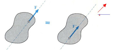
Principle of transmissibility of forces
The state of rest of motion of a rigid body is unaltered if a force acting in the body is replaced by another force of the same magnitude and direction but acting anywhere on the body along the line of action of the replaced force.
For example the force F acting on a rigid body at point A. According to the principle of transmissibility of forces, this force has the same effect on the body as a force F applied at point B.


The following two points should be considered while using this principle.
1. In engineering mechanics we deal with only rigid bodies. If deformation of the body is to be considered in a problem. The law of transmissibility of forces will not hold good.
2. By transmission of the force only the state of the body is unaltered, but not the internal stresses which may develop in the body Therefore this law can be applied only to problems in which rigid bodies are involved.

Basic quantities used in engineering mechanics


Basic quantities used in engineering mechanics
In engineering mechanics length, mass, time and force are basic quantities
1. Length
In engineering mechanics length is needed to locate the position of a particle and to describe the size of physical system. Some important length conversions factors
1cm = 10 mm 1 m = 100 cm 1 m = 1000 mm
1 m = 3.2808 (feet) 1 m = 39.37 Inch 1 Mile = 1.609 km
2. Mass
Mass is the property of matter by which we can compare the action of one body with that of another. This property manifests itself as gravitational attraction between two bodies and provides a quantitative measure of the resistance of matter to a change in velocity. Some important mass conversion factors are given below
1 Kg = 2.204 lbm
3. Time
Time is the measure of the succession of events and is a basis quantity in dynamic. Time is not directly involved in the analysis of statics problems but it has importance in dynamics.


Fundamental concept of Engineering Mechanics


The following are the fundamental concept used in the engineering mechanics
1. Force
In general force is a Push or Pull, which creates motion or tends to create motion, destroy or tends to destroys motion. In engineering mechanics force is the action of one body on another. A force tends to move a body in the direction of its action, A force is characterized by its point of application, magnitude, and direction, i.e. a force is a vector quantity.
Units of force
The following force units are frequently used.
A. Newton
The S.I unit of force is Newton and denoted by N. which may be defined as
1N = 1 kg. 1 m/s2
B. Dynes
Dyne is the C.G.S unit of force.
1 Dyne = 1 g. 1 cm/s2
One Newton force = 102 dyne
C. Pounds
The FPS unit of force is pound.
1 lbf = 1 lbm. 1ft/s2
One pound force = 4.448 N
One dyne force = 2.248 x 10ˉ6 lbs
2. Space
Space is the geometrical region occupied by bodies whose positions are described by linear and angular measurement relative to coordinate systems. For three dimensional problems there are three independent coordinates are needed. For two dimensional problems only two coordinates are required.
3. Particle
A particle may be defined as a body (object) has mass but no size (neglected), such body cannot exists theoretically, but when dealing with problems involving distance considerably larger when compared to the size of the body. For example a bomber aeroplane is a particle for a gunner operating from ground. In the mathematical sense, a particle is a body whose dimensions are considered to be near zero so that it analyze as a mass concentrated at a point. A body may tread as a particle when its dimensions are irrelevant to describe its position or the action of forces applied to it. For example the size of earth is insignificant compared to the size of its orbits and therefore the earth can be modeled as a particle when studying its orbital motion. When a body is idealized as a particle, the principles of mechanics reduce to rather simplified form since the geometry of the body will not be involved in the analysis of the problem.
4. Rigid Body
A rigid body may be defined a body in which the relative positions of any two particles do not change under the action of forces means the distance between two points/particles remain same before and after applying external forces. As a result the material properties of any body that is assumed to be rigid will not have to be considered while analyzing the forces acting on the body. In most cases the actual deformations occurring in the structures, machines, mechanisms etc are relatively small and therefore the rigid body assumption is suitable for analysis


Engineering Mechanics And Classification of Mechanics


MECHANICS And Classification of Mechanics
Mechanics can be defined as the branch of physics concerned with the state of rest or motion of bodies that subjected to the action of forces.
OR
It may be defined as the study of forces acting on body when it is at rest or in motion is called mechanics.
Classification of Mechanics
The engineering mechanics are classified as shown

Classification of Mechanics

BRANCHES OF MECHANICS:
Mechanics can be divided into two branches.
1. Static. 2. Dynamics.
a) Statics
It is the branch of mechanics that deals with the study of forces acting on a body in equilibrium. Either the body at rest or in uniform motion is called statics
b) Dynamics:
It is the branch of mechanics that deals with the study of forces on body in motion is called dynamics. It is further divided into two branches.
i) Kinetics ii) kinematics.
i) Kinetics
It is the branch of the dynamics which deals the study of body in motion under the influence of force i.e. is the relationship between force and motion are considered or the effect of the force are studied
ii) Kinematics:
It is the branch of the dynamics that deals with the study of body in motion without considering the force.

Wednesday, 1 April 2020

Effects of automobile pollution on environment and human beings

Introduction:- The major source of air pollution are flue gases, emissions from refineries and factories etc. on one hand and 60% of air pollution are due to automobile exhaust emission in other hand. The I. C Engine exhaust contains several pollutants in the form of oxides of Nitrogen (Nox) which are toxic and facing severe criticism. If the concentration exceeds 100 ppm in enclosed space, if may even cause death.

Effects of automobile pollution on environment and human beings:

  • The Oxides of Nitrogen together with hydro carbons react in the presence of sunlight and form
  • Polto chemical smog. If effects the bad condition on crops Animals,Birdscracking in rubber etc.
  • It Causes eyes irritation, objectionable odour.
  • It causes reduction in visibility, results traffic hazards.
  • The soot particles in the exhaust gases settle down on buildings and trees if may thus spoils appearance of buildings in the long run.
  • The exhaust smoke is dangerous for health and causes troubles in breathing Problems.


Types of Automobile emissions:
The vehicle emissions contains following types of pollutants

  • Exhaust emissions
  • Carbon Monoxide
  • Un burnt hydro carbons
  • Oxides of Nitrogen
  • Lead oxides
  • Sulphur dioxide
  • Smoke
  • Evaporative Emissions
  • Carburettor
  • fuel tank
  • petrol bunks


Crank case blow by from the crank case hydro carbons are emitted
Measurement of Percentage of Pollutions from petrol and Diesel Vehicles with the help of exhaust gas analyzers
By using exhaust gas analyzer the measurement of percentage of following pollutants from petrol and Diesel Vehicles
Treatment of Exhaust gases by using catalytic converter
The exhaust gases from the engine are passed through CATALYTIC
CONVENTER
A catalytic converter is a cylindrical unit about the size of small silencer and it installed in to the exhaust system of a vehicle. It is placed between the exhaust manifold and silencer in the exhaust system of a vehicle. Inside the converter there is a honey corn structure of a ceramic or metal . Which is coated with aluminum base material and there after a second coat of precious metals platinum, palladium or rhodium or combination of the same.

The second coating serves as a catalyst. A catalyst is a substance which causes a chemical reaction that normally does not happen in to the given conditions. As a result catalytic reaction as the exhaust gases pass over the converter substance, toxic gases such as co, the and NOX are converted in to harmless CO2,H2 and N2 . There are two types of catalytic converters.

A Two way converter which is used to control only CO and HC commissions by oxidation
A Three way converter Which is used almost in all petrol cars It controls CO and HC by oxidation
As well as NOX by reduction.

PAINTING OF AUTOMOBILE

Introduction: The corrosive nature of a metal used in a motor body construction, necessitate the application of an anti corrosion coating. For this reason the painting should be done.

Function of Painting:
1. It reduces the corrosion and protect the vehicle body.
2. It is used for cleanliness.
3. It is used for esthetic appearance.
4. It is used to reduce the friction due to the aerodynamic drag and allow the vehicle in stream lining.
5. It is used for identification purpose.

Requirements of Good Painting:
1. It should be anticorrosive nature.
2. It should protect the hidden parts also from the corrosion.
3. It should have esthetic appearance.
4. It should be smooth finish for stream lining.
5. It must reduce the aerodynamic drag.

Main Constituents of paints:
1. Pigments
2. Drying oil
3. Thinners
4. Dry Extenders
5. Plasticizers
6. Resins.

Reason for failures of paints:
1. Not proper cleaning of body before painting
2. Not covering dents or spots.
3. Not using of proper good quality paint
4. Not applied the pretreatment with zinc phosphate.

Different Types of Painting
1. Spray paint
2. Hand paint

Spray Painting procedure: Now-a-days spray paintings are largely use. The procedure is as follows:
1. First of all the old paint should be scrapped with the help of scrappers
2. If there is nail or any obstruction they will be removed with the help of pincers
3. The removal of old paint must be by application of caustic soda solution and spirit solutions.
4. In some portions heating is necessary with the help of blow lamp for removal of old paint.
5.The surface should be cleaned from dirt, dust, rust, grease etc.
6. The surface should maintain perfect level from any kind of bends.
7. Then once again clean with red oxide.
8. After wards duco paints or delux paints or required colour may be sprayed on the vehicle as the primary coating.
9. After first coating is over we must see the variations of the surface clearly and apply second coating and it will finish the painting job and gives beautiful appearance.
10. Then decoration and letter writing finishes the body paint.
11. Finally polish the vehicle thoroughly.

AIR CONDITIONING OF MOTOR VEHICLE

Necessity of Automobile Air-Conditioning: Due to varying conditions of heating, ventilating, cooling, dehumidification in the atmosphere at various places, it is necessary to be conditioned the air in the automobiles. To maintain human comfort and improve internal atmosphere in an enclosed space, proper control of freshness temperature, humidity and cleanliness of air is required. For this reason Automobile air-conditioning is necessary in the vehicles.

Construction and working of Passenger car Air – Conditioning:
The main components of Auto Air- Condition are:
1. Compressor
2. Magnetic clutch
3. Condenser
4. Receiver or dehydrator
5. Expansion valve
6. Evaporator
7. Such on throttling valve

Compressor: The compressor in the Auto Air- Condition system is belt-driven engine crankshaft pulley. A magnetic clutch engages the compressor shaft. When the voltage is applied to the compressor clutch coil was sufficient the compressor and pulley rotates together as one unit. When the voltage is interrupted the pulley, disengages automatically, causes compressor to stop. The low – pressured, high temperature, vaporized refrigerant enter in to the compressor and it increases the pressure of about 20kg/cm² and 100ºc temp, and pushes into the condenser. In the compressor the refrigerant never reaches its liquid state.

Magnetic Clutch: The electrically controlled magnetic clutch is housed in pulley assembly and a switch is on the controlling panel. This clutch is engaged or disengaged depending upon the temperature of the air. Bellow 40 ºF. The compressor cannot be operated. Above 55ºF this switch closes and completes the circuit to the compressor clutch.

Condenser: It is usually placed in front of the car and it is looks like a Fin-andtube radiator. The condenser receives heated and compressed gas from the compressor and is cooled by the air passing across the condenser. The refrigerant now in the form of high pressure liquid which is fed in to the receiver drier Unit.

Reservoir or Dehydrator: The refrigerant stored under pressure in the Receiverdrier. The drier removes any traces of moisture present in the system to avoid freezing of moisture at low temperature and thus clogging the lines. It causes running troubles.

Expansion Valve: In the expansion valve high pressure liquid is converted into low pressure liquid then the refinement flow in to the evaporator

Evaporator: The evaporator unit where the cooling effect is obtained is usually located inside the passenger compartment bellow the dash board. A high capacity blower circulates the air in the in the car interior across the evaporator coils, and the drops the temperature of the air inside the passenger compartment. The heat picked by the refrigerant goes back to the compressor in the vapour form, where the refrigerant is again compressed to a high pressure and the cycle starts again.

Suction throttle valve: It ensures that the refrigerant the evaporator says at such a pressure that the evaporator core surface temperature does not fall bellow the freezing point of water (0°c), thus preventing ice formation in the evaporator.

SEAT DOOR AND WINDOW MECHANISM OF CAR BODY

Construction and working of door lock mechanism:
There are different methods to door lock or unlock mechanisms:
1. With a key
2. By pressing the unlock button inside the car
3. By using the combination lock on the outside of the door
4. By pulling up the knob on the inside of the door.
5. With a keyless – entry remote control.
6. By a signal from a control center.

In most of the cars having power door locks, the lock/unlock switch actually sends power to the actuators that unlock the doors. But in more complicated system having several ways to lock and unlock the doors, the body controller decides when to do the unlocking. Body controller is a computer in the car. Besides locks it takes care of many little things that makes your car friendlier
e.g., it make sure the interior lights stay on until the car is started, it beeps if you leave your head lights on or leave the key in the ignition. Etc., In power locks, body controller monitors all the possible sources ‘lock’ or ‘unlock’ signals e.g. it monitors a door – mounted touch pad and unlock the doorsn when the correct mode is entered, it monitors a radio frequency and unlocks the doors when it receives the connect digital code from the radio transmitter in the key fob and also monitor the switches inside the car. When it receives a signal from any of these sources, it provides power to the actuator that locks or unlocks the doors.
The detailed power lock mechanism, in the door the actuator is portioned bellow the latch. A rod connects the actuator to the latch and another rod connects the latch to the knob that sticks up out of the top of the door. When the actuator moves the latch up, it connects the outside door handle to the opening mechanism. When the latch is down the outside door handle is disconnected from the mechanism so that the door cannot be opened. To unlock the door, the body controller supplies power to the doorlock actuator for a timed interval. The door lock actuator is a simple device. It consists of a small electric motor which turns a series of spur geans that operate a rack. The rack pulls the knob up or pushes it down, thus opening or closing the lock.

Construction and Working of Manual Window Regulating Mechanism:
The window glass winding mechanism included in the door construction. When the handle is turning one direction, the toothed quadrant which in turn moves the window carnivore. The glass fitted on the window carrier which moves up and down as per the direction of rotation of the toothed quadrant either clock wise or anti clock wise.

Construction and Working of Seat Adjusting Mechanism:
It is different form from the passenger seat . Bucket tupe of seat commonly used. This type of seat is adjustable towards or away from the steering wheel or control pedals in order to suit driver’s varying lengths of the legs. In this arrangement rails are fixed to the frame. Frame is fixed with bolts to slide on a rails squire to the floor. A lever projected to laterally to the seat cushion. This engages with slide catch for seat position adjustment. The return spring of the rocker again engages with the side catch. The lever is left free after the adjustment of seat.
Powered By Blogger